
Cable testing
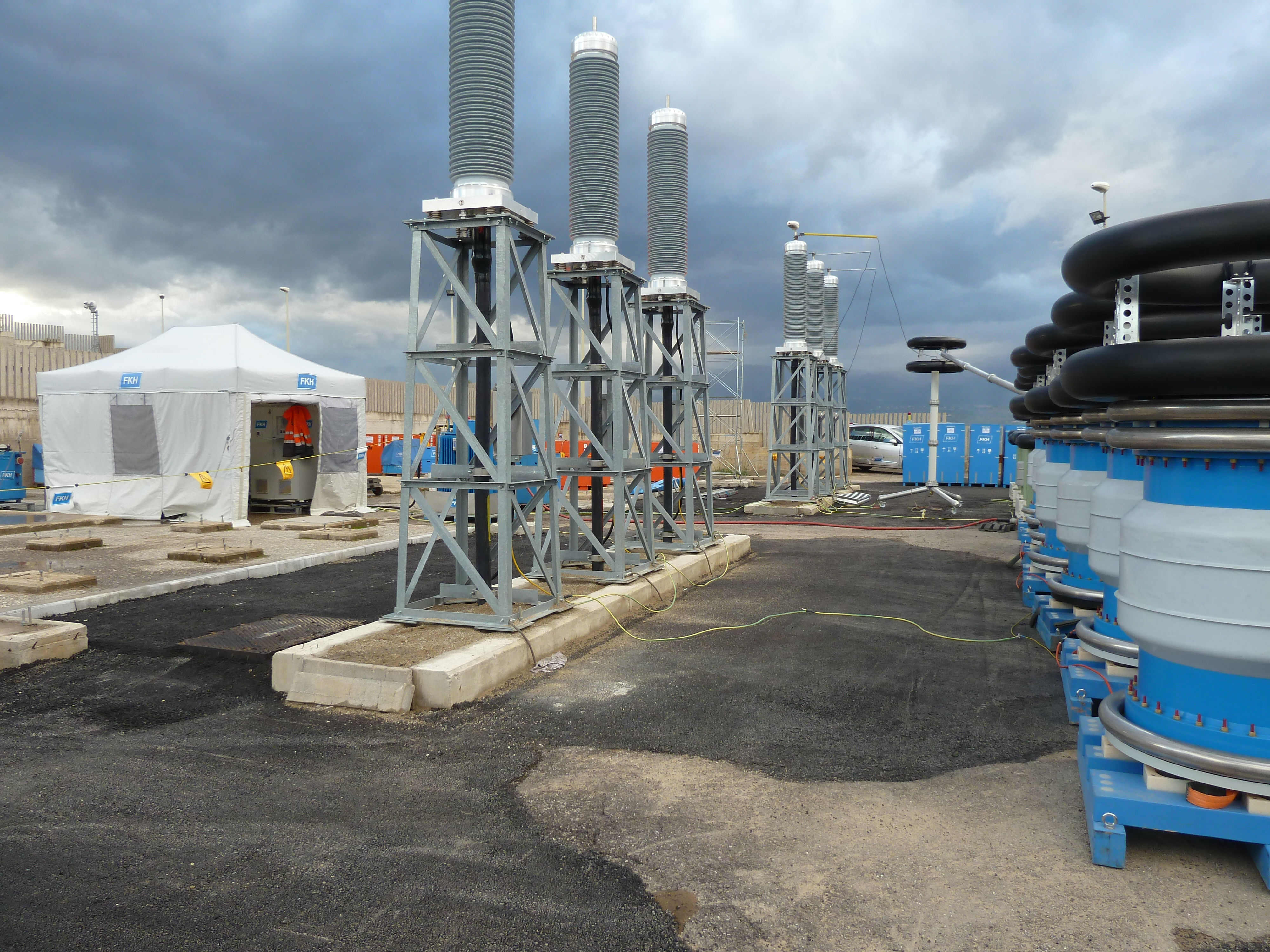
High-voltage resonance test on a 275 kV cable connection
Proof of proper assembly and installation of cable systems is the primary consideration when carrying out on-site voltage testing of high-voltage cable connections.
The on-site AC voltage testing technology for high-voltage cables that is now used throughout the world was developed jointly by the Swiss Federal Institute of Technology Zurich (ETH) and FKH, and was introduced by FKH in the 1980s. It is based on the series resonance principle with tuneable frequency. Various other diagnostic methods, including partial discharge (PD) measurements in particular, are offered in addition to voltage testing.
High-voltage series-resonant testing of cable systems
Prior to commissioning a new cable system, or after the completion of major conversion work on an existing system, voltage
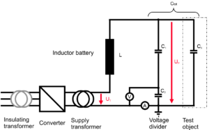
Diagram of a series-resonant system
testing is recommended before starting to operate the system. The aim is to exclude the following faults in particular:
- Assembly errors in cable terminations or joints
- Damage to the cable sheath or the semiconding screen
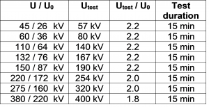 In compliance with CENELEC HD 632 and in divergence from IEC 60840 and/or 62067, FKH recommends that a higher test voltage should be applied to cables, but for a reduced testing duration. This recommendation is based on FKH’s lengthy experience of testing.
In the test circuit, an inductance L with a high quality factor is connected in series to the capacitanc Cx. Under resonance conditions, a voltage Up builds up over the test object that is considerably greater than the voltage UT of the supply transformer. The test frequency is obtained with the following formula:![]()
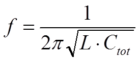
Thanks to its modular inductances, the test system can be configured for a sufficiently high test frequency to ensure that voltage transformers do not reach magnetic saturation; this eliminates the need to remove them for the test.
Advantages over other methods
- Power supply required is low
- Voltage at the test object is sinusoidal and free of harmonics
- Minimal energy release at the fault location in case of test object breakdown
- If the inductances are connected in parallel, the frequency can be increased so that voltage transformers can be included in the testing
- Additional cable connections and other equipment connected via switchgear can also be included in the testing
Partial discharge measurement and other diagnostic methods
A partial discharge measurement is recommended as an additional measure for important cable sections and higher voltage levels. This involves specific inspections of the cable terminations and joints in order to identify insulation faults. In this way, it is possible to detect flaws that have not yet caused an immediate breakdown, but which harbour the risk of an unexpected insulation failure.
FKH uses the following partial discharge test methods and coupling types:
- Conventional, via a coupling capacitor
- With partial discharge sensors integrated into the fittings (joints, terminations)
- Via current sensors on the cable shielding
- With acoustic emission sensors
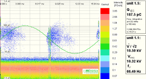
Partial discharge level during a voltage test
The modern partial discharge measurement instruments used by FKH allow synchronous measurements at different points. To capture all partial discharges simultaneously, fibre-optic (OWG) connections must be installed between all the sensors in advance.
For oil-insulated cables and in the medium-voltage grid, FKH also performs C-tgδ measurements as well as measurements of the polarisation and depolarisation currents (PDC).