
Grounding measurements
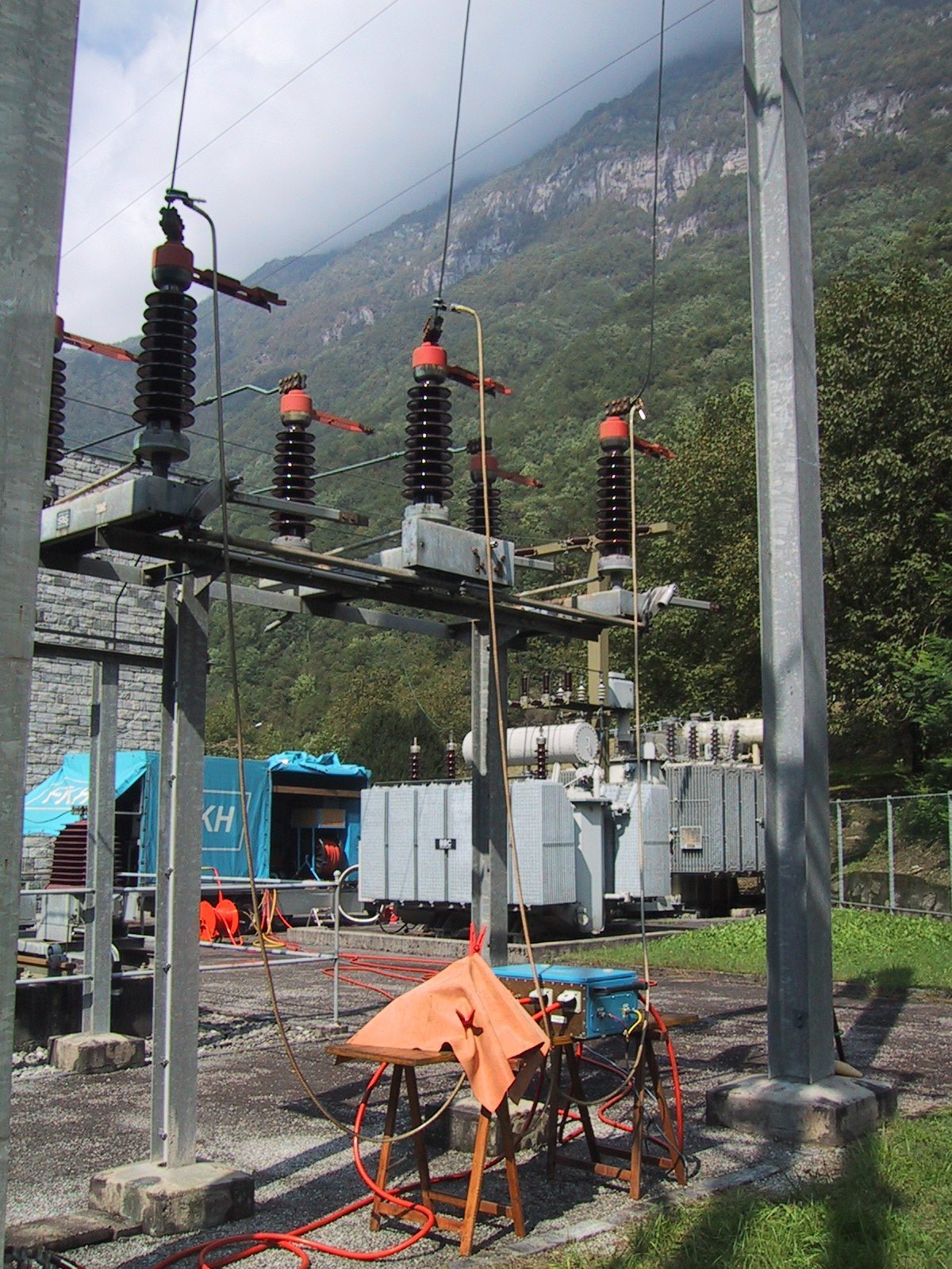
Grounding measurement on an outdoor installation
FKH offers grounding measurements using a compact mobile testing system to analyse and assess the effectiveness of grounding systems for substations and other power installations.
With the current-voltage method, a ground fault current IM (50 A to 200 A) is generated by a mobile 42 kVA frequency converter and is fed into a defined ground fault loop that includes the grounding system. If possible, a swiched off overhead line or cable line (grounded at the remote station) is used for the ground fault loop. If the current source cannot be set up at the substation to be inspected, the feed can also be positioned on the remote side.
The current between the grounding systems of the substation under inspection and the station with the remote grounding generates grounding voltages UE1 and UE2 respectively, making it possible to measure differential voltages and determine the current distribution.
All the measurement results are extrapolated to the maximum ground fault current of the installation under inspection.
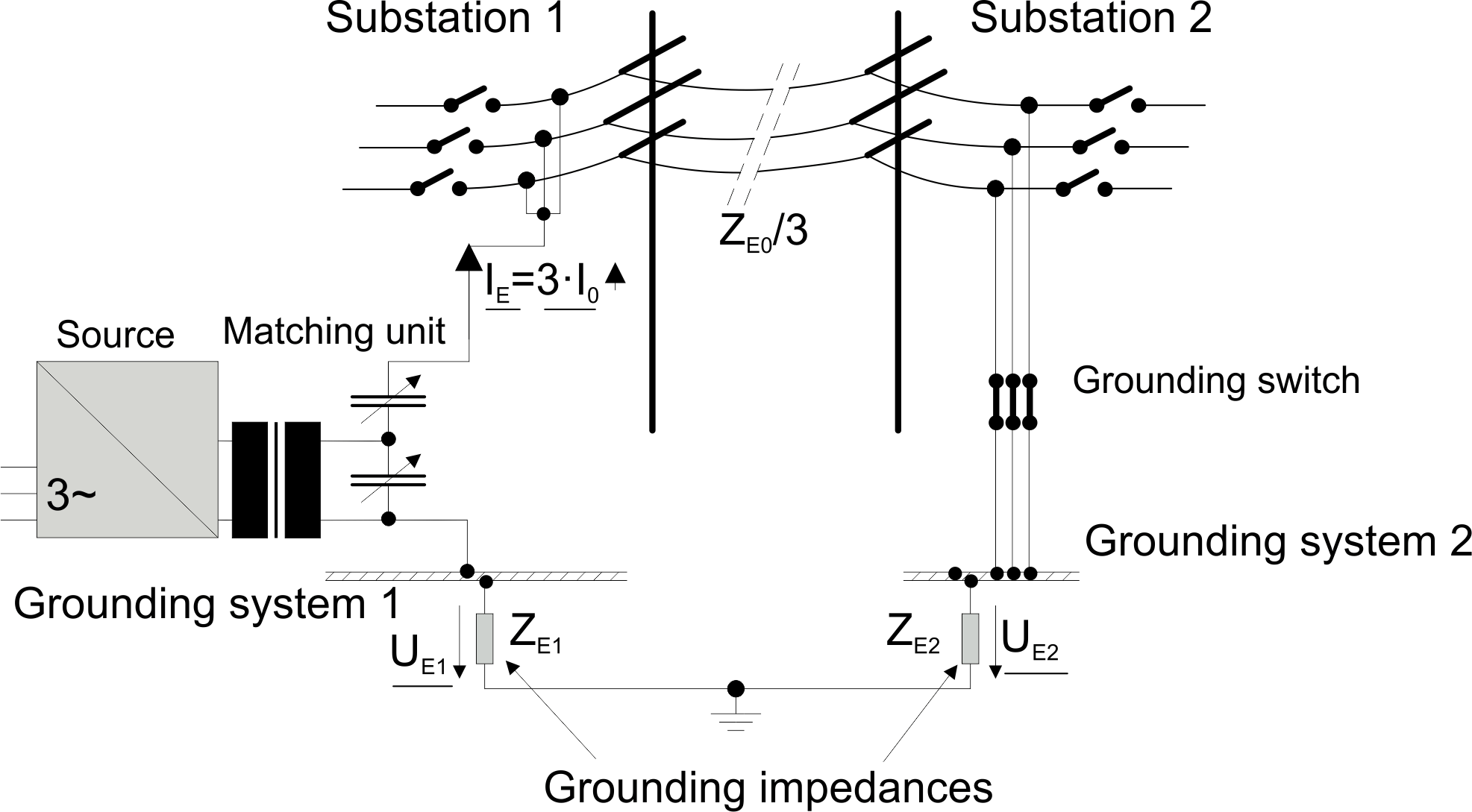
The FKH converter is operated at a frequency different from the operating frequency of the grid (e.g. 70 Hz for 50 Hz systems). For impedance matching, the supply source is connected to the test line via a matching transformer and a variable compensation capacitance.
Because the experimental ground fault current differs from the operating frequency, it is possible to distinguish clearly between the ground currents generated for test purposes and the operational ground currents, ground voltages and induction voltages.
In order to determine the differential voltages, FKH uses suitable highly selective filters that eliminate any influence on the measurement results due to system operation at 50 Hz or railway currents at 16.7 Hz.
Service scope for a grounding measurement
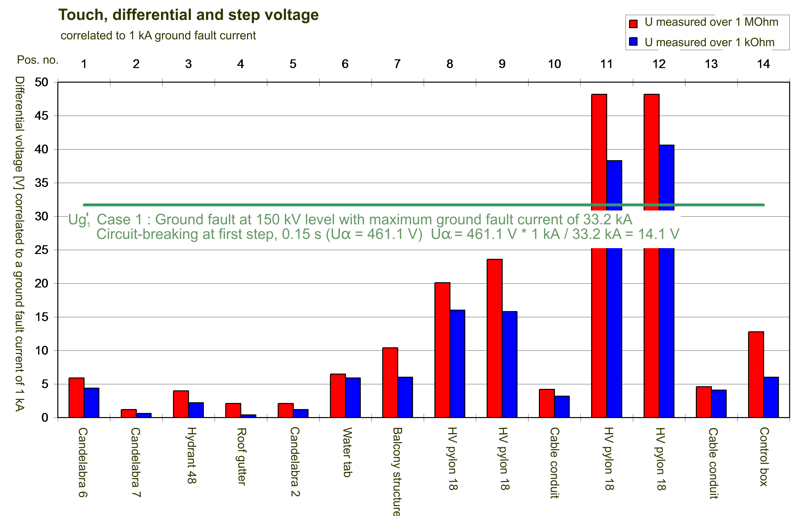
 Differential voltage determination
Touch, step and differential voltages are measured inside the system and in the transition zone. The basis for the assessment of the measured values that are determined is the applicable Ordinance for power installations (March 1994 edition, status as at 1 July 2012) and/or SEV (Electrosuisse) standard SNG483755, 2015: “Grounding as a protective measure in electrical power installations”.
System ground impedance measurement
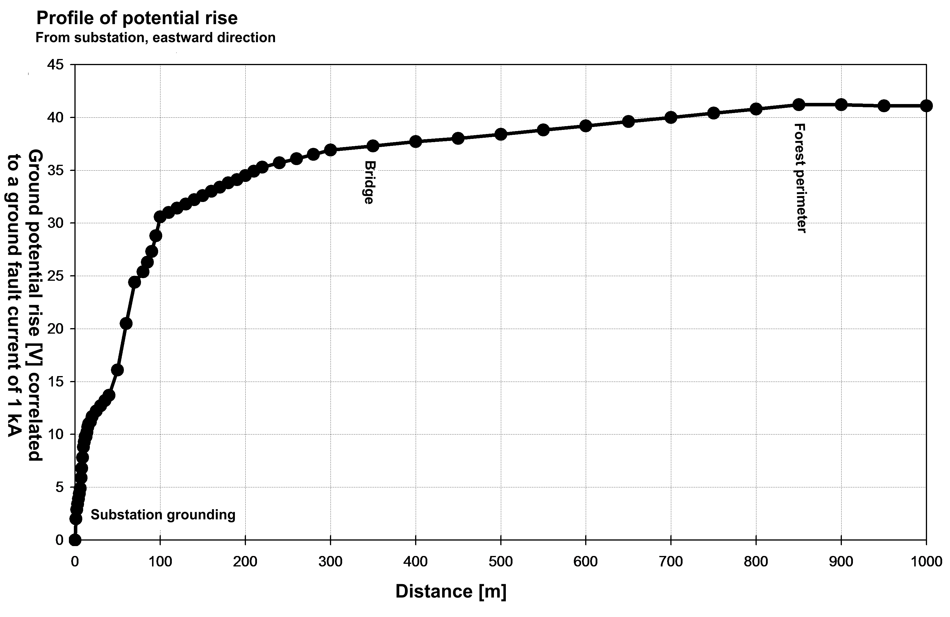
 The profile of the potential rise is determined by measuring one or more radial voltage profiles as far as the uninfluenced reference ground range. The potential difference between the reference ground and the grounding system is correlated to the supplied ground fault current. This ratio is used for an approximate determination of the system’s effective ground impedance.
Measurement of ground fault current distribution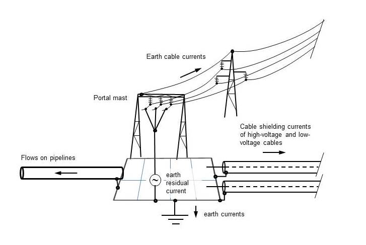
The ground fault current component (magnitude and phase) is determined on all lines and metallic connections exiting from the installation area. These include (but are not limited to) ground connections, ground wires of overhead lines, grounded shielding for power and control cables, pressure pipelines and railway lines. This investigation provides information about the distribution of the currents in case of a ground fault. The effectiveness of the ground connections is verified. In addition, it is possible to detect possible interference problems due to ground currents, especially for secondary control cables.
Line impedance measurement
Both zero sequence and positive sequence impedance are measured on the line used for the ground fault loop.
Documentation and report
Once the grounding measurement has been completed, a report is drawn up with the evaluation of the measurement results. The effectiveness of the grounding system and the differential voltages occurring in case of a ground fault are assessed and documented. Remedial actions are suggested if the touch, step and differential voltages are unacceptably high.